This manual, part number 1283270GT (Revision A2, November 2018), details components for Z-45/25, Z-45/25J, and DC models.
It’s frequently updated; access the latest figures online. Serial numbers, like Z452506-12345, are crucial for identification and support.

Manual Revision & Updates
Genie Industries consistently updates this parts manual (Part No. 1283270GT) to reflect engineering changes, new components, and improved clarity. The November 2018 revision (A2) represents a significant update, but ongoing modifications are common. To ensure you possess the most current information, Genie strongly recommends downloading updated figures directly from their official website.
This digital approach allows for immediate access to the latest schematics, wiring diagrams, and part numbers, crucial for accurate maintenance and repair. Regularly checking for updates—particularly when addressing complex issues—prevents errors and ensures safety. The manual covers models Z-45/25, Z-45/25J, and DC variants, so verifying the applicable serial number range is vital before applying any information.
Applicable Models
This Genie Z-45/25 Parts Manual (Part No. 1283270GT) comprehensively covers the Z-45/25, Z-45/25J, and DC model variations. It’s essential to confirm your specific machine’s model and serial number before utilizing any information within this document. Discrepancies between the manual and your equipment can lead to incorrect part replacements or improper repair procedures.
The manual’s applicability is also determined by the serial number range. For instance, certain components, like the turntable cover (310.3), may only apply to machines from serial number Z4525D-10803 onwards. Always cross-reference your machine’s serial number (e.g., Z452506-12345) with the manual’s specifications to guarantee compatibility and accurate servicing.
Serial Number Identification
Accurate serial number identification is paramount when using this Genie Z-45/25 Parts Manual. The serial number, such as Z452506-12345, uniquely identifies your machine and dictates which parts and diagrams are applicable. It’s crucial for ordering the correct replacements and ensuring compatibility.
Refer to your machine’s data plate to locate the serial number; it’s typically found on the chassis or turntable. This manual is frequently updated, and component changes often correlate with specific serial number breaks. The manual explicitly states to “Search by the make and model…enter your machine’s serial number” on the Genie website for precise part identification. Utilizing the incorrect parts based on a misidentified serial number can compromise safety and machine functionality.
Understanding the Genie Z45/25 Components
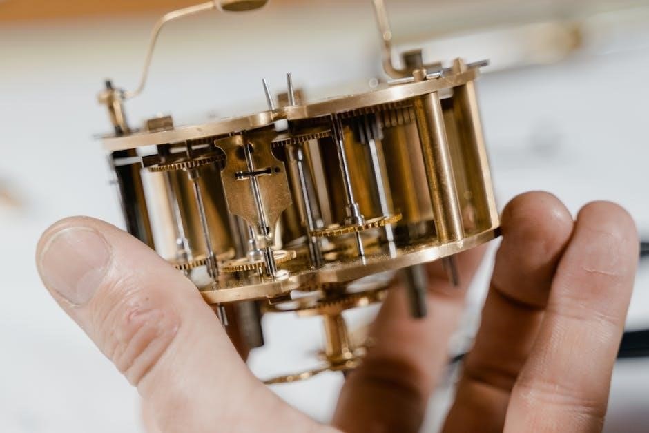
This section details the Z-45/25’s key assemblies: turntable, platform control box, hydraulic, and electrical systems. Diagrams and schematics aid in component comprehension;
Turntable Assembly
The turntable assembly is a critical rotating component of the Genie Z-45/25, enabling platform articulation and reach. This assembly incorporates various parts, including the turntable cover (specifically part 310.3 for tank side configurations with Kubota engines, from serial number Z4525D-10803 onwards).
Proper functionality relies on bearings, seals, and the overall structural integrity of the turntable. Maintenance involves inspecting these components for wear and tear, ensuring smooth rotation, and lubricating as needed. Detailed diagrams within the parts manual illustrate the exploded view of the turntable assembly, showcasing each individual part and its corresponding number for easy identification during repair or replacement. Referencing the serial number is vital to ensure compatibility with the correct parts.
Platform Control Box Wiring Diagrams
The Genie Z-45/25 parts manual provides comprehensive platform control box wiring diagrams, essential for troubleshooting electrical issues and performing repairs. These diagrams (referenced as CE diagrams, specifically diagram number ES0274) detail the connections between various components within the control box, including switches, sensors, and the control system itself.
Understanding these diagrams is crucial for diagnosing malfunctions related to platform movement, emergency stops, and other control functions. The manual offers specific wiring schematics for different configurations, ensuring accurate repairs. Always disconnect power before working on the electrical system. Proper identification of wires and connectors, guided by the diagrams, is paramount for safe and effective maintenance. Refer to part number 1268530GT for related documentation.
Hydraulic System Components
The Genie Z-45/25 parts manual meticulously details the hydraulic system’s components, vital for understanding lift and movement mechanisms. This includes the hydraulic pump, cylinders, hoses, valves, and the hydraulic oil tank. Diagrams illustrate the arrangement and interconnection of these parts, aiding in repair and maintenance procedures.
Proper functioning of the hydraulic system is critical for safe operation. The manual assists in identifying specific components for replacement, ensuring compatibility. Understanding the system allows technicians to diagnose leaks, pressure issues, and cylinder malfunctions effectively. Maintenance procedures, such as fluid level checks and filter replacements, are also supported by the detailed component information. Always follow safety precautions when working with hydraulic systems, as high pressure can be dangerous.
Electrical System Schematics
The Genie Z-45/25 parts manual provides comprehensive electrical system schematics, essential for troubleshooting and repair of electrical faults. These schematics detail wiring harnesses, connectors, control circuits, and component locations. Electrical schematic number ES0274 is referenced within the documentation, aiding in precise identification of circuits.
Understanding these diagrams is crucial for diagnosing issues with platform controls, drive motors, and safety systems. The manual supports identifying specific wire colors, connector types, and component functions. Technicians can use these schematics to trace circuits, locate shorts or opens, and perform accurate repairs. Always disconnect the battery before working on the electrical system and adhere to all safety guidelines. Proper electrical maintenance ensures reliable and safe machine operation.

Key Parts & Replacement
Locate parts using the serial number on the Genie website. Diagrams detail wire harnesses, ORFS/37 JIC fittings, and tank side components (Kubota engine option) for easy replacement.
Wire Harness Diagrams
Detailed wire harness diagrams are essential for accurate electrical system maintenance and repair on the Genie Z-45/25. These diagrams illustrate the complete routing and connection points of all wiring within the machine, facilitating troubleshooting and component replacement.
Understanding these schematics allows technicians to quickly identify damaged wires, faulty connections, or incorrect wiring configurations. The diagrams clearly depict wire colors, connector types, and pin assignments, ensuring proper restoration of electrical functionality.
Accessing the most current wire harness diagrams is crucial, as revisions occur with manual updates. Genie Industries provides these diagrams online, allowing users to download the latest versions specific to their machine’s serial number. Proper use of these diagrams minimizes downtime and ensures safe operation of the Z-45/25.
Tank Side Components (Kubota Engine Option)
For Genie Z-45/25 models equipped with the Kubota engine, specific components are located on the tank side. These include items detailed in section 310.3 of the parts manual, specifically the turntable cover. Identifying these parts requires referencing the serial number; components differ from SN Z4525D-10803 onwards.
Proper maintenance of these tank-side components is vital for reliable engine operation and overall machine performance. This section of the manual provides exploded views and part numbers for easy identification and ordering of replacements.
Technicians should consult the diagrams carefully to ensure correct installation and alignment. Utilizing genuine Genie parts guarantees compatibility and maintains the machine’s original specifications. Regular inspection of these components helps prevent potential issues and extends the lifespan of the Kubota engine.
ORFS & 37 JIC Fittings & Hose Ends
The Genie Z-45/25 parts manual provides detailed information regarding ORFS (O-Ring Face Seal) and 37 JIC (Joint Industry Conference) fittings and hose ends. These are critical components within the hydraulic system, ensuring leak-free connections and efficient fluid transfer.
Correct identification of these fittings is paramount when performing repairs or replacements. The manual offers diagrams illustrating the various types and sizes used throughout the machine. Using the appropriate fittings is essential to maintain system pressure and prevent failures.
Genie emphasizes the importance of utilizing compatible hose ends alongside the fittings to guarantee a secure and reliable connection. Referencing the parts manual and utilizing the correct part numbers will ensure optimal performance and safety when working with the hydraulic system.

Maintenance & Repair Information
Machine unladen weight and rated work load (500 lb / 227 kg) are key specs. Maximum allowable inclination data aids safe operation and repair procedures.
Machine Unladen Weight & Rated Work Load
Understanding the Genie Z-45/25’s weight characteristics is paramount for safe operation, transportation, and maintenance. The machine’s unladen weight directly impacts towing capacity and handling requirements. Crucially, the rated work load, including occupants, is specified as 500 lbs / 227 kg.
Exceeding this limit compromises stability and can lead to hazardous situations. This information is vital when assessing job site suitability and planning lifts. Always verify the load weight before operation. Proper weight distribution is also essential for maintaining balance and preventing tipping. Refer to the operator’s manual for detailed guidance on load capacity calculations and safe operating procedures. Ignoring these guidelines can result in equipment damage or personal injury.
Maximum Allowable Inclination
Maintaining stability is critical when operating the Genie Z-45/25 on inclines. The maximum allowable inclination of the machine must never be exceeded to prevent tipping or loss of control. While the specific degree isn’t explicitly stated in the provided text, understanding this limitation is vital for safe operation.
Always assess the ground conditions before maneuvering on any slope. Uneven terrain or hidden obstacles can significantly affect stability. Operators should be thoroughly trained on recognizing and avoiding hazardous inclines. Refer to the comprehensive operator’s manual for the precise maximum allowable inclination specification for your specific model and serial number. Prioritize safety by always operating within the prescribed limits and utilizing appropriate safety measures, such as outriggers when necessary.
Product Support Resources
Genie Industries provides extensive support for the Z-45/25 series. For immediate assistance, contact Genie Industries directly at 18340 NE 76th Street, Redmond, WA 98052, USA. A key resource is the Genie website, where you can download updated figures and parts diagrams.

Locating the correct parts is streamlined through their online platform: search by machine make and model, then input your machine’s serial number to access detailed parts diagrams. This ensures accurate identification of part numbers for replacements. Furthermore, the website offers access to operator’s manuals and other crucial documentation. Prior to any maintenance or repair, consult Product Support to ensure compatibility and proper procedures are followed, maximizing machine uptime and safety.

Specific Part Locations
Detailed diagrams pinpoint platform, drive, and steering system components. Refer to sections 310.3 for turntable covers (Kubota engine option) and wiring harness diagrams.
Platform Components
The platform assembly incorporates crucial safety and operational elements. This section details the location and part numbers for components like the platform control box, wiring harnesses, and associated sensors.
Understanding the Platform Control Box Wiring Diagram (CE), referenced as part number 1268530GT, is vital for troubleshooting electrical issues.
Inspect the platform for proper functionality of all switches, emergency stop buttons, and guardrails. Diagrams illustrate the arrangement of these parts, aiding in accurate identification during maintenance or replacement.
Ensure all connections are secure and wiring is intact to prevent operational hazards;
Refer to the manual for specific torque specifications when reassembling platform components.
Proper maintenance of platform components directly impacts operator safety and machine performance.
Drive Components
Drive components are fundamental to the Genie Z45/25’s mobility and performance; This section details parts related to the machine’s traction and movement. Key elements include the drive motors, wheel assemblies, and associated hardware.
Detailed diagrams illustrate the arrangement of these components, facilitating accurate identification during repair or replacement procedures.
Inspect drive tires for wear and tear, ensuring proper inflation for optimal traction.
Regularly check the drive motors for signs of damage or leaks, addressing any issues promptly to prevent operational failures.
Refer to the manual for specific torque specifications when servicing drive components. Maintaining these parts is crucial for safe and efficient operation, contributing to the machine’s overall reliability. Machine unladen weight impacts drive system stress.
Steering System Parts
The Genie Z45/25 steering system ensures precise maneuverability and control. This section outlines the components responsible for directional changes, including the steering cylinder, steering links, and associated hardware. Detailed illustrations aid in identifying each part for maintenance and repair.
Proper steering functionality is vital for operator safety and efficient operation. Regularly inspect steering linkages for wear, damage, or looseness, and tighten or replace components as needed.
Check the steering cylinder for leaks and ensure smooth operation; Maximum allowable inclination affects steering stability. Refer to the parts manual for specific torque specifications when servicing the steering system. Maintaining these components guarantees responsive steering and contributes to the machine’s overall performance and safety.
Troubleshooting & Safety
Common issues require careful diagnosis; always prioritize safety precautions. Consult this manual for solutions and adhere to ANSI A92.5/CAN B.354.4 standards.
Common Issues & Solutions
Hydraulic system malfunctions are frequently reported, often stemming from low fluid levels or contaminated oil; regular checks and fluid replacement are vital. Electrical issues, indicated by unresponsive controls, may require inspecting wiring diagrams (Part No. 1268530GT) and checking connections within the platform control box. Drive system problems, like reduced speed or erratic movement, could involve worn drive components. Turntable issues, particularly with the cover (Part No. 310.3 for Kubota engine options from SN Z4525D-10803), necessitate inspection for damage or obstruction.
Always refer to the electrical schematic (ES0274) when diagnosing electrical faults. Ensure proper fitting of ORFS and 37 JIC fittings and hose ends to prevent leaks. Prioritize safety; disconnect power before any electrical work. Consult Product Support for complex issues and always use genuine Genie parts.
Safety Precautions
Prioritize personal safety when working on the Genie Z45/25. Always disconnect the battery before performing any electrical repairs to avoid shock hazards. Never exceed the machine’s rated work load (500 lb / 227 kg), and adhere to the maximum allowable inclination to prevent tipping. Inspect all components for damage before use, particularly hydraulic hoses and fittings, ensuring they are correctly tightened.
Refer to the Operator’s Manual (Part No. 1268530GT) for comprehensive safety guidelines. Ensure the work area is clear of obstructions and personnel. Use appropriate personal protective equipment (PPE), including safety glasses and gloves. Be cautious when working with hydraulic systems, as pressurized fluid can cause injury. Consult Genie Industries for any safety concerns or clarifications.
Genie Industries Contact Information
For parts inquiries, technical support, or to report issues with your Genie Z45/25, contact Genie Industries directly. Their headquarters are located at 18340 NE 76th Street, Redmond, WA 98052, USA. Product Support resources are available to assist with identifying correct parts and troubleshooting. Always have your machine’s serial number (e.g., Z452506-12345) readily available when contacting support, as it’s crucial for accurate assistance.
Visit the Genie website to search for parts diagrams and download updated figures for your specific model. Ensure you are referencing the correct manual version (Part No. 1283270GT). For ANSI A92.5 and CAN B.354.4 compliance information, consult the relevant documentation or contact Genie’s compliance department. Prompt and accurate information will expedite your request.